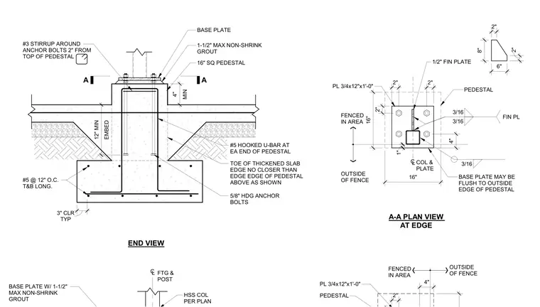
A hollow structural section column per plan is welded to a three-quarter by twelve-inch by one-foot-zero-inch base plate with a one-half-inch fin plate. The base plate is supported by a maximum of one and one-half inches of non-shrink grout over a sixteen-inch square concrete pedestal. Four five-eighths-inch hot-dip galvanized anchor bolts embed into the concrete footing with number three stirrups around the anchor bolts two inches from the top of the pedestal, and number five hooked u-bars at each end of the pedestal. The concrete footing is reinforced with number five longitudinal bars at twelve inches on center top and bottom with three inches of typical clearance.
PL 3/4x12"x1'-0" 3/16 3/16 3/16 FIN PL 1/2" FIN PLATE A-A PLAN VIEW AT EDGE PEDESTAL 16" 16" 4" 2" 2" OUTSIDE OF FENCE FENCED IN AREA 2" BASE PLATE MAY BE FLUSH TO OUTSIDE EDGE OF PEDESTAL 1" C L COL & PLATE A A MIN 4" 1-1/2" MAX NON-SHRINK GROUT BASE PLATE #3 STIRRUP AROUND ANCHOR BOLTS 2" FROM TOP OF PEDESTAL #5 HOOKED U-BAR AT EA END OF PEDESTAL 5/8" HDG ANCHOR BOLTS #5 @ 12" O.C. T&B LONG. TYP 3" CLR 16" SQ PEDESTAL TOE OF THICKENED SLAB EDGE NO CLOSER THAN EDGE EDGE OF PEDESTAL ABOVE AS SHOWN END VIEW EMBED 12" MIN 8" 6" 2" 2" C L HSS COL PER PLAN BASE PLATE W/ 1-1/2" MAX NON-SHRINK GROUT FTG & POST 4" 2" FENCED IN AREA OUTSIDE OF FENCE PL 3/4x12"x1'-0" PEDESTAL
Members view this detail in full resolution, download the CAD files (SVG, PDF), and can adapt it in the built-in CAD editor — export DXF, DWG, or PDF.
Start membership