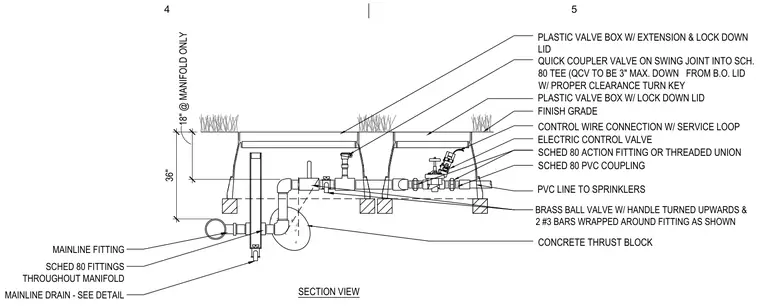
An underground irrigation manifold assembly sits below finish grade within plastic valve boxes equipped with extensions and lock-down lids. A quick coupler valve on a swing joint ties into a Schedule 80 tee, positioned three inches maximum down from the bottom of the lid with proper clearance for a turn key. An electric control valve connects via Schedule 80 PVC couplings, Schedule 80 action fittings or threaded unions, and a brass ball valve with its handle turned upwards. Two number 3 reinforcing bars wrap around the fitting as shown adjacent to a concrete thrust block. A mainline drain connects through Schedule 80 fittings throughout the manifold to PVC lines leading to sprinklers, with control wires featuring service loops.
4 5 SECTION VIEW PLASTIC VALVE BOX W/ EXTENSION & LOCK DOWN LID QUICK COUPLER VALVE ON SWING JOINT INTO SCH. 80 TEE (QCV TO BE 3" MAX. DOWN FROM B.O. LID W/ PROPER CLEARANCE TURN KEY PLASTIC VALVE BOX W/ LOCK DOWN LID FINISH GRADE CONTROL WIRE CONNECTION W/ SERVICE LOOP ELECTRIC CONTROL VALVE PVC LINE TO SPRINKLERS SCHED 80 PVC COUPLING SCHED 80 ACTION FITTING OR THREADED UNION CONCRETE THRUST BLOCK 36" 18" @ MANIFOLD ONLY MAINLINE DRAIN - SEE DETAIL MAINLINE FITTING SCHED 80 FITTINGS THROUGHOUT MANIFOLD BRASS BALL VALVE W/ HANDLE TURNED UPWARDS & 2 #3 BARS WRAPPED AROUND FITTING AS SHOWN
Members view this detail in full resolution, download the CAD files (SVG, PDF), and can adapt it in the built-in CAD editor — export DXF, DWG, or PDF.
Start membership