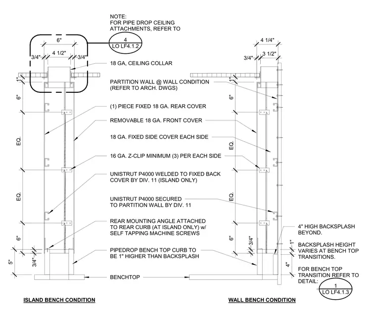
Laboratory pipe drop chase assemblies for both island bench and wall bench conditions comprise a one-piece fixed 18-gauge rear cover, a removable 18-gauge front cover, and 18-gauge fixed side covers. Unistrut P4000 channels are welded to the fixed back cover for island conditions and secured to the partition wall for wall conditions. Assembly components are held together with 16-gauge Z-clips spaced at a minimum of three per side, with a rear mounting angle attached to the rear curb using self-tapping machine screws at island conditions. The bench top curb is positioned one inch higher than the backsplash, featuring an 18-gauge ceiling collar at the top penetration.
ISLAND BENCH CONDITION WALL BENCH CONDITION NOTE: FOR PIPE DROP CEILING ATTACHMENTS, REFER TO 18 GA, CEILING COLLAR PARTITION WALL @ WALL CONDITION (REFER TO ARCH. DWGS) (1) PIECE FIXED 18 GA. REAR COVER REMOVABLE 18 GA. FRONT COVER 18 GA. FIXED SIDE COVER EACH SIDE UNISTRUT P4000 WELDED TO FIXED BACK COVER BY DIV. 11 (ISLAND ONLY) 16 GA. Z-CLIP MINIMUM (3) PER EACH SIDE UNISTRUT P4000 SECURED TO PARTITION WALL BY DIV. 11 REAR MOUNTING ANGLE ATTACHED TO REAR CURB (AT ISLAND ONLY) w/ SELF TAPPING MACHINE SCREWS PIPEDROP BENCH TOP CURB TO BE 1" HIGHER THAN BACKSPLASH BENCHTOP LO LF4.1.2 4 4" HIGH BACKSPLASH BEYOND. BACKSPLASH HEIGHT VARIES AT BENCH TOP TRANSITIONS. FOR BENCH TOP TRANSITION REFER TO DETAIL: LO LF4.1.3 1 5" 3/4" 6" EQ. EQ. 6" 1" 6" 3/4" 4 1/2" 3/4" 1" 4" 3/4" 6" EQ. EQ. 6" 1" 4 1/4" 3 1/2" 3/4"
Members view this detail in full resolution, download the CAD files (SVG, PDF), and can adapt it in the built-in CAD editor — export DXF, DWG, or PDF.
Start membership