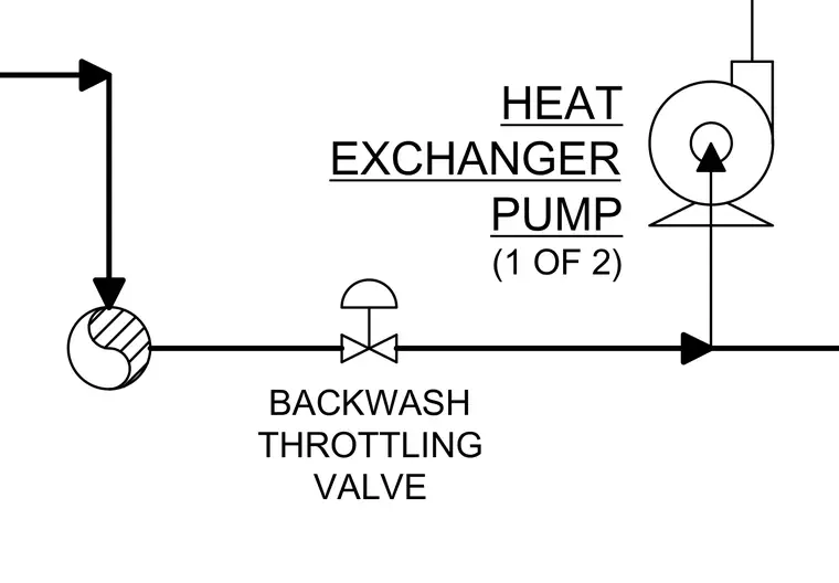
The schematic details a process piping layout featuring a backwash throttling valve positioned upstream of a heat exchanger pump. Directional arrows indicate the flow path of the fluid through the piped connections. A secondary pump or equipment component is identified as part one of two for the heat exchanger system.
Members view this detail in full resolution, download the CAD files (SVG, PDF), and can adapt it in the built-in CAD editor — export DXF, DWG, or PDF.
Start membership