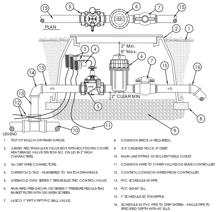
The assembly is housed within a jumbo rectangular valve box set atop four common bricks and six inches of three-quarter-inch crushed rock. Water enters through a main line fitting with a solvent-weld outlet connected to a schedule 40 polyvinyl chloride pipe and a ninety-degree elbow. A one-inch schedule 80 toe nipple connects to a one-inch brass electric control valve, followed by a pressure regulating basket filter with a mesh screen and a one-inch polyvinyl chloride ball valve. Control and common wires from the controller connect via waterproof wire connectors and feature an identification tag. The outgoing schedule 40 polyvinyl chloride pipe extends to the drip system at a specified depth using forty-five-degree elbows.
LEGEND 1. TOP OF MULCH OR FINISH GRADE. 2. JUMBO RECTANGULAR VALVE BOX WITH BOLT DOWN COVER. HEAT BRAND VALVE STATION NO. ON LID IN 2" HIGH CHARACTERS. 3. 3m DBY WIRE CONNECTORS. 4. CHRISTY'S I.D.TAG - NUMBERED TO MATCH DRAWINGS. 5. GRISWOLD DWS SERIES 1" BRASS ELECTRIC CONTROL VALVE. 6. RAIN BIRD PRB-QKCHK-100 SERIES 1" PRESSURE REGULATING BASKET FILTER WITH 200 MESH SCREEN. 7. LASCO 1" FIPT X FIPT PVC BALL VALVE.. 8. COMMON BRICK (4 REQUIRED). 9. 3/4" CRUSHED ROCK. 6" DEEP. 10. MAIN LINE FITTING W/SOLVENT WELD OUTLET. 11. COMMON WIRE TO OTHER VALVES ON SAME CONTROLLER. 12. CONTROL/COMMON WIRES FROM CONTROLLER. 13. PVC SCHEDULE 40 PIPE. 14. PVC SxS 90° ELL. 15. 1" SCHEDULE 80 TOE NIPPLE. 16. SCHEDULE 40 PVC PIPE TO DRIP SYSTEM - ANGLE PIPE TO SPECIFIED DEPTH WITH 45° ELLS. 2'' CLEAR MIN. 2'' Min. 6'' Max. PLAN
Members view this detail in full resolution, download the CAD files (SVG, PDF), and can adapt it in the built-in CAD editor — export DXF, DWG, or PDF.
Start membership