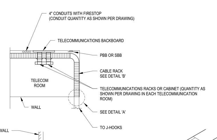
A telecommunications room layout features a wall-mounted telecommunications backboard paired with primary or secondary bonding busbars. Four-inch conduits equipped with firestop penetrate the wall assembly as specified on drawings. Cable trays route data cables from the backboard to telecommunications racks or cabinets. Cable management continues along walls using J-hooks per associated detail references.
TELECOMMUNICATIONS BACKBOARD PBB OR SBB 4" CONDUITS WITH FIRESTOP (CONDUIT QUANTITY AS SHOWN PER DRAWING) TELECOMMUNICATIONS RACKS OR CABINET (QUANTITY AS SHOWN PER DRAWING IN EACH TELECOMMUNICATION ROOM) CABLE RACK SEE DETAIL 'B' TELECOM ROOM SEE DETAIL 'A' WALL TO J-HOOKS WALL
Members view this detail in full resolution, download the CAD files (SVG, PDF), and can adapt it in the built-in CAD editor — export DXF, DWG, or PDF.
Start membership