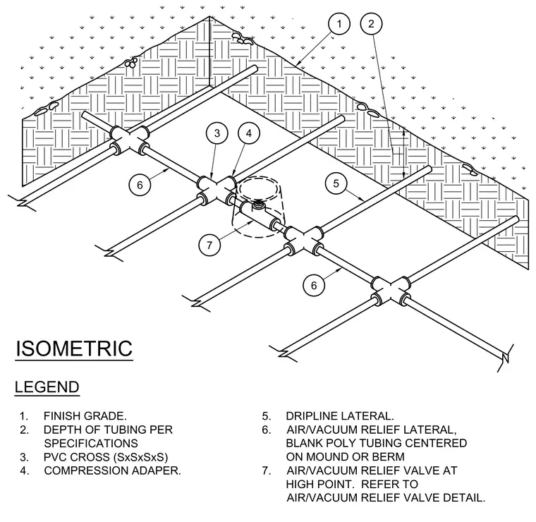
An air and vacuum relief lateral is installed below the finish grade at a depth determined by project specifications. Polyvinyl chloride cross fittings connect with compression adapters to distribute the network. Blank polyethylene tubing forms the air and vacuum relief lateral centered on the mound or berm, operating alongside standard dripline laterals. An air and vacuum relief valve is positioned at the system high point.
1 2 3 4 7 5 6 6 ISOMETRIC 1. FINISH GRADE. 2. DEPTH OF TUBING PER SPECIFICATIONS 3. PVC CROSS (SxSxSxS) 4. COMPRESSION ADAPER. 5. DRIPLINE LATERAL. 6. AIR/VACUUM RELIEF LATERAL, BLANK POLY TUBING CENTERED ON MOUND OR BERM 7. AIR/VACUUM RELIEF VALVE AT HIGH POINT. REFER TO AIR/VACUUM RELIEF VALVE DETAIL. LEGEND
Members view this detail in full resolution, download the CAD files (SVG, PDF), and can adapt it in the built-in CAD editor — export DXF, DWG, or PDF.
Start membership