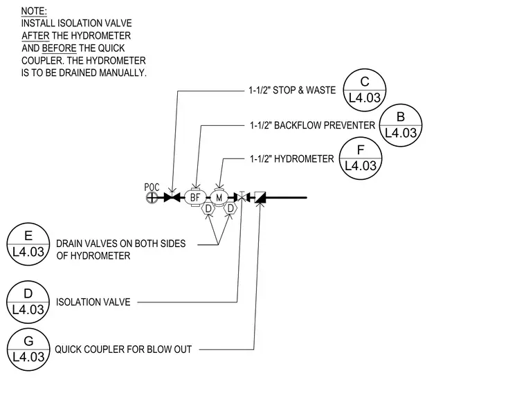
An irrigation service line diagram shows a one-and-a-half-inch stop and waste valve connected to a one-and-a-half-inch backflow preventer, followed by a one-and-a-half-inch hydrometer. Drain valves are installed on both sides of the hydrometer for manual drainage. An isolation valve is positioned after the hydrometer and before a quick coupler for blow out. All PVC fittings and pipe shall be used.
NOTE: INSTALL ISOLATION VALVE AFTER THE HYDROMETER AND BEFORE THE QUICK COUPLER. THE HYDROMETER IS TO BE DRAINED MANUALLY. 1-1/2" STOP & WASTE 1-1/2" BACKFLOW PREVENTER 1-1/2" HYDROMETER QUICK COUPLER FOR BLOW OUT ISOLATION VALVE DRAIN VALVES ON BOTH SIDES OF HYDROMETER G L4.03 F L4.03 D L4.03 E L4.03 B L4.03 C L4.03
Members view this detail in full resolution, download the CAD files (SVG, PDF), and can adapt it in the built-in CAD editor — export DXF, DWG, or PDF.
Start membership