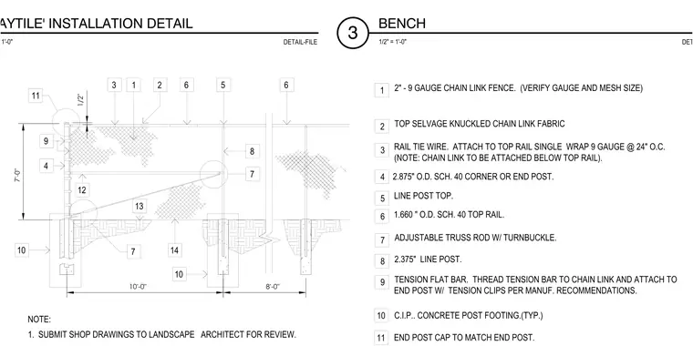
The assembly consists of a two-inch, nine-gauge chain link fabric secured with a top selvage knuckled edge and attached to the top rail using nine-gauge tie wires spaced at twenty-four inches on center. The framework utilizes 2.875-inch outside diameter schedule 40 corner or end posts alongside 2.375-inch line posts and a 1.660-inch outside diameter schedule 40 top rail. An adjustable truss rod with a turnbuckle provides bracing, while a tension flat bar threaded to the mesh attaches to the end post using tension clips per manufacturer recommendations. All posts are anchored into cast-in-place concrete post footings.
3 BENCH 1/2" = 1'-0" DETAIL-FILE 3 1 2 6 5 6 8 7 9 4 11 10 14 12 13 11 10 9 8 7 6 5 4 3 2 1 NOTE: 10'-0" 8'-0" 10 7 1. SUBMIT SHOP DRAWINGS TO LANDSCAPE ARCHITECT FOR REVIEW. 2" - 9 GAUGE CHAIN LINK FENCE. (VERIFY GAUGE AND MESH SIZE) TOP SELVAGE KNUCKLED CHAIN LINK FABRIC RAIL TIE WIRE. ATTACH TO TOP RAIL SINGLE WRAP 9 GAUGE @ 24" O.C. (NOTE: CHAIN LINK TO BE ATTACHED BELOW TOP RAIL). 2.875" O.D. SCH. 40 CORNER OR END POST. LINE POST TOP. 1.660 " O.D. SCH. 40 TOP RAIL. ADJUSTABLE TRUSS ROD W/ TURNBUCKLE. 2.375" LINE POST. TENSION FLAT BAR. THREAD TENSION BAR TO CHAIN LINK AND ATTACH TO END POST W/ TENSION CLIPS PER MANUF. RECOMMENDATIONS. C.I.P.. CONCRETE POST FOOTING.(TYP.) END POST CAP TO MATCH END POST. 'PLAYTILE' INSTALLATION DETAIL 1 1/2" = 1'-0" DETAIL-FILE
Members view this detail in full resolution, download the CAD files (SVG, PDF), and can adapt it in the built-in CAD editor — export DXF, DWG, or PDF.
Start membership