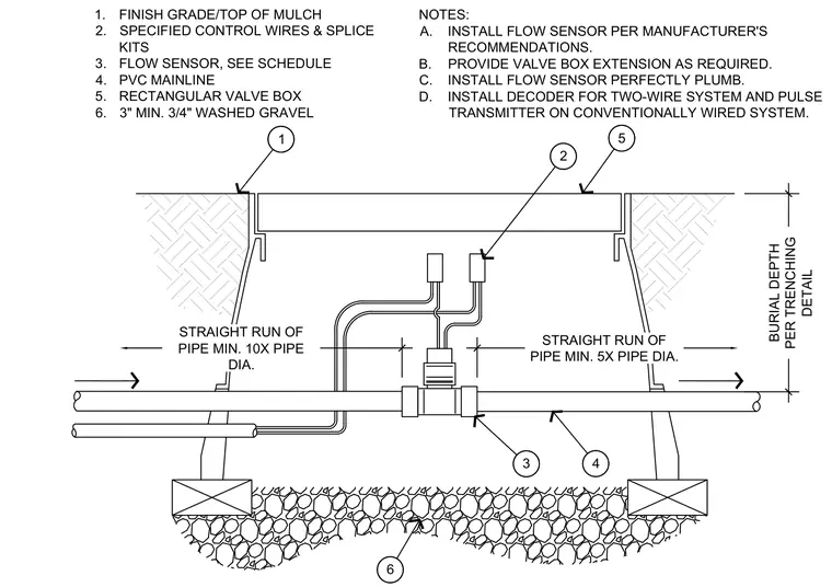
An inline flow sensor is plumbed directly into a PVC mainline pipe at a burial depth determined by the trenching detail. The sensor sits within a rectangular valve box set flush with the finish grade and top of mulch. A three-inch minimum bed of three-quarter-inch washed gravel supports the pipe assembly and provides drainage. Specified control wires and splice kits connect to the sensor, with a decoder installed for a two-wire system or a pulse transmitter on a conventionally wired system. Straight runs of pipe are maintained at a minimum of ten times the pipe diameter upstream and five times the pipe diameter downstream of the sensor.
1. FINISH GRADE/TOP OF MULCH 2. SPECIFIED CONTROL WIRES & SPLICE KITS 3. FLOW SENSOR, SEE SCHEDULE 4. PVC MAINLINE 5. RECTANGULAR VALVE BOX 6. 3" MIN. 3/4" WASHED GRAVEL STRAIGHT RUN OF PIPE MIN. 10X PIPE DIA. BURIAL DEPTH PER TRENCHING DETAIL STRAIGHT RUN OF PIPE MIN. 5X PIPE DIA. NOTES: A. INSTALL FLOW SENSOR PER MANUFACTURER'S RECOMMENDATIONS. B. PROVIDE VALVE BOX EXTENSION AS REQUIRED. C. INSTALL FLOW SENSOR PERFECTLY PLUMB. D. INSTALL DECODER FOR TWO-WIRE SYSTEM AND PULSE TRANSMITTER ON CONVENTIONALLY WIRED SYSTEM. 1 2 3 4 5 6
Members view this detail in full resolution, download the CAD files (SVG, PDF), and can adapt it in the built-in CAD editor — export DXF, DWG, or PDF.
Start membership