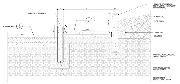
The assembly consists of a cast-in-place concrete retaining wall retaining a sloped rubber surface on one side and a planting soil bed on the other. A four-foot-wide concrete path with a one-point-five percent slope spans between the concrete retaining walls, which feature six-inch-thick stems and variable heights. A four-inch perforated pipe wrapped in filter fabric rests within drain rock behind the upper retaining wall to manage subsurface drainage. Below the structure, a compacted aggregate base and compacted subgrade are placed per civil drawings, with concrete reinforcement sized per structural drawings.
9 L601 RUBBER SURFACE 1.67% 1.5% VARIES 6" 6" VARIES 4' - 0" CONCRETE RETAINING WALL COMPACTED AGGREGATE BASE, SEE CIVIL DRAWING CIP-1 REINFORCEMENT, SEE STRUCTURAL DRAWING 1 L601 COMPACTED SUBGRADE, SEE CIVIL DRAWING CONCRETE RETAINING WALL SEE STRUCTURAL DRAWINGS FOR REINFORCEMENTS 6" FILTER FABRIC 4" PERF. PIPE DRAIN ROCK PLANTING SOIL
Members view this detail in full resolution, download the CAD files (SVG, PDF), and can adapt it in the built-in CAD editor — export DXF, DWG, or PDF.
Start membership