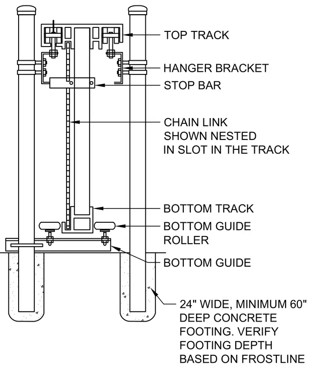
The sliding gate assembly is supported by a top track and a bottom track with chain link nested in the slot in the track. Hanger brackets connect the upper mechanism to vertical posts, while a stop bar limits travel. Bottom guide rollers flank the lower track to maintain alignment. The entire assembly is anchored by concrete footings that measure twenty-four inches wide by a minimum of sixty inches deep, with depth subject to verification based on local frostline requirements.
TOP TRACK STOP BAR CHAIN LINK SHOWN NESTED IN SLOT IN THE TRACK BOTTOM TRACK BOTTOM GUIDE ROLLER BOTTOM GUIDE HANGER BRACKET 24" WIDE, MINIMUM 60" DEEP CONCRETE FOOTING. VERIFY FOOTING DEPTH BASED ON FROSTLINE
Members view this detail in full resolution, download the CAD files (SVG, PDF), and can adapt it in the built-in CAD editor — export DXF, DWG, or PDF.
Start membership