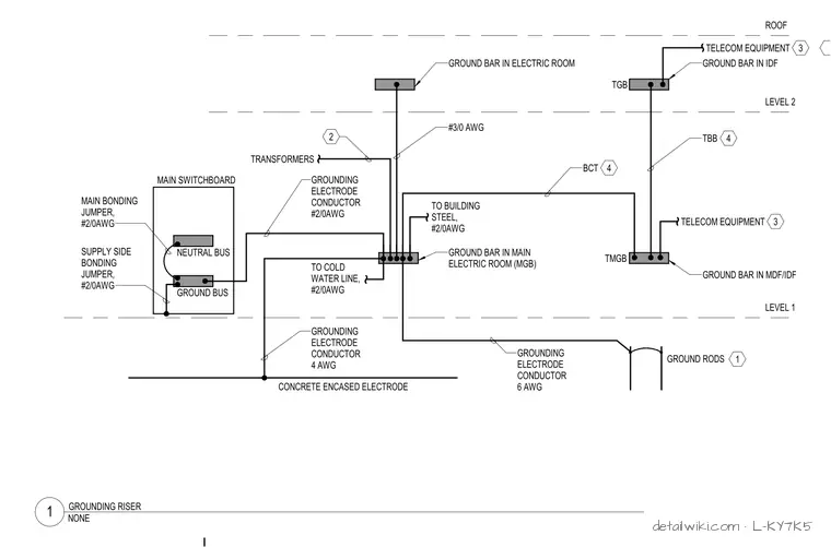
The diagram displays the electrical grounding system riser layout across multiple building levels, from Level 1 up to the roof. It details specific conductor sizes, such as #2/0 AWG and #3/0 AWG, connecting the main electrical room ground bar to the main switchboard, concrete-encased electrode, cold water line, structural steel, and telecom grounding bars (TMGB and TGB). Ground rods and various bonding jumpers are also indicated.
Text on the drawing
ROOF LEVEL 2 LEVEL 1 GROUNDING ELECTRODE CONDUCTOR #2/0AWG GROUNDING ELECTRODE CONDUCTOR 4 AWG TO COLD WATER LINE, #2/0AWG CONCRETE ENCASED ELECTRODE 1 2 MAIN BONDING JUMPER, #2/0AWG NEUTRAL BUS GROUND BUS GROUND BAR IN ELECTRIC ROOM GROUND BAR IN MDF/IDF GROUND RODS GROUND BAR IN MAIN ELECTRIC ROOM (MGB) TRANSFORMERS SUPPLY SIDE BONDING JUMPER, #2/0AWG GROUNDING ELECTRODE CONDUCTOR 6 AWG TO BUILDING STEEL, #2/0AWG TGB TMGB GROUND BAR IN IDF MAIN SWITCHBOARD TELECOM EQUIPMENT 3 4 TBB 4 BCT TELECOM EQUIPMENT 3 #3/0 AWG NONE 1 GROUNDING RISER
Members view this detail in full resolution, download the CAD files (SVG, PDF), and open any detail in the built-in CAD editor to edit and export DXF or DWG.
Sign in to subscribe