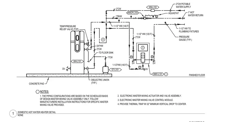
The domestic hot water heater connects to a two-inch cold water potable water supply and a one-inch hot water return line over a finished floor concrete pad. A temperature and pressure relief valve is installed on the water heater with a drain line to a floor sink, and dielectric unions are used on the piping connections typically. An expansion tank and an electronic master mixing valve assembly regulate the system temperatures between one hundred twenty and one hundred forty degrees Fahrenheit. An aquastat and water meter tie into the system along with pressure gauges typically placed throughout the piping configuration. A thermal trap with a thirty-two-inch minimum vertical drop to center is provided on the hot water line.
NOTES: A DV T DV T DV T FINISHED FLOOR 1. THE PIPING CONFIGURATIONS ARE BASED ON THE SCHEDULED BASIS OF DESIGN MASTER MIXING VALVE ASSEMBLY ONLY. FOLLOW MANUFACTURERS INSTALLATION INSTRUCTIONS FOR SPECIFIC MASTER MIXING VALVE PROVIDED. HWCP-L101 2"CW POTABLE WATER SUPPLY 1-1/2" HW TO PLUMBING FIXTURES ET-L101 1-1/2" HW (140 F) PRESSURE GAUGE (TYP.) 1" HOT WATER RETURN DV WH-L101 TO FLOOR SINK CONCRETE PAD DIELECTRIC UNION (TYP.) 2. ELECTRONIC MASTER MIXING ACTUATOR AND VALVE ASSEMBLY. MMV-L101 1 1-1/2" HW (120 F) 1-1/2"HW (140 F) 2"CW 3 2 4 4. PROVIDE THERMAL TRAP WI 32" MINIMUM VERTICAL DROP TO CENTER. 3. ELECTRONIC MASTER MIXING VALVE CONTROL MODULE. 1"RHW 2"CW 2"CW 1"CW TEMP/PRESSURE RELIEF VALVE (TYP) 3/4"HW AQUASTAT WM-L102 NONE 1 DOMESTIC HOT WATER HEATER DETAIL
Members view this detail in full resolution, download the CAD files (SVG, PDF), and can adapt it in the built-in CAD editor — export DXF, DWG, or PDF.
Start membership