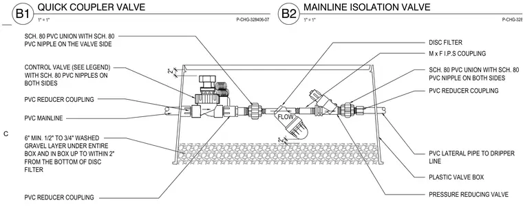
A PVC mainline feeds into a control valve equipped with schedule 80 PVC nipples on both sides and a reducer coupling. Downstream of the control valve, a schedule 80 PVC union connects to a disc filter followed by a pressure reducing valve and an M x F I.P.S coupling. The entire assembly is housed within a plastic valve box set over a minimum 6-inch layer of 1/2-inch to 3/4-inch washed gravel that extends up to within 2 inches from the bottom of the disc filter. A PVC lateral pipe exits the box to supply the dripper line.
QUICK COUPLER VALVE 1" = 1" B1 P-CHG-328406-07 MAINLINE ISOLATION VALVE 1" = 1" B2 P-CHG-328406-05 FLOW 2" 2" PRESSURE REDUCING VALVE PLASTIC VALVE BOX PVC LATERAL PIPE TO DRIPPER LINE PVC REDUCER COUPLING SCH. 80 PVC UNION WITH SCH. 80 PVC NIPPLE ON BOTH SIDES M x F I.P.S COUPLING DISC FILTER SCH. 80 PVC UNION WITH SCH. 80 PVC NIPPLE ON THE VALVE SIDE CONTROL VALVE (SEE LEGEND) WITH SCH. 80 PVC NIPPLES ON BOTH SIDES PVC REDUCER COUPLING PVC MAINLINE 6" MIN. 1/2" TO 3/4" WASHED GRAVEL LAYER UNDER ENTIRE BOX AND IN BOX UP TO WITHIN 2" FROM THE BOTTOM OF DISC FILTER PVC REDUCER COUPLING C
Members view this detail in full resolution, download the CAD files (SVG, PDF), and can adapt it in the built-in CAD editor — export DXF, DWG, or PDF.
Start membership