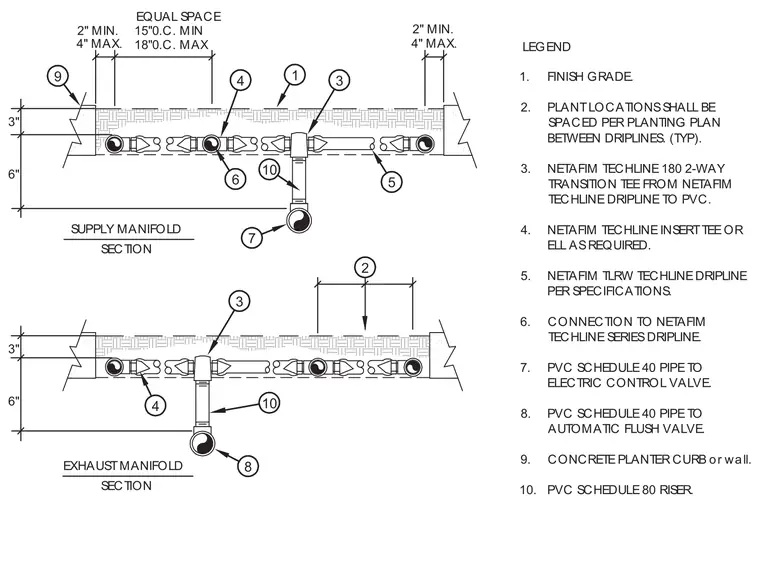
An irrigation manifold layout details supply and exhaust connections within a concrete planter curb or wall bounded by finish grade. Netafim Techline dripline series tubing connects via insert tees or ells and transitions to PVC schedule 40 pipe leading to electric control valves and automatic flush valves. A PVC schedule 80 riser connects the main line to a Netafim 180 two-way transition tee. Clearances maintain two inches minimum to four inches maximum from the planter wall to the first dripline, with fifteen to eighteen inches on center spacing between driplines.
1. FINISH GRADE. 2. PLANT LOCATIONS SHALL BE SPACED PER PLANTING PLAN BETWEEN DRIPLINES. (TYP). 3. NETAFIM TECHLINE 180 2-WAY TRANSITION TEE FROM NETAFIM TECHLINE DRIPLINE TO PVC. 4. NETAFIM TECHLINE INSERT TEE OR ELL AS REQUIRED. 5. NETAFIM TLRW TECHLINE DRIPLINE PER SPECIFICATIONS. 6. CONNECTION TO NETAFIM TECHLINE SERIES DRIPLINE. 7. PVC SCHEDULE 40 PIPE TO ELECTRIC CONTROL VALVE. 8. PVC SCHEDULE 40 PIPE TO AUTOMATIC FLUSH VALVE. 9. CONCRETE PLANTER CURB or wall. 10. PVC SCHEDULE 80 RISER. 8 EXHAUST MANIFOLD SECTION 4 10 LEGEND SUPPLY MANIFOLD SECTION 7 6 2" MIN. 9 4" MAX. 15"0.C. MIN 4 2 10 5 1 3 2" MIN. 4" MAX. 18"0.C. MAX EQUAL SPACE 3 3" 6" 3" 6"
Members view this detail in full resolution, download the CAD files (SVG, PDF), and can adapt it in the built-in CAD editor — export DXF, DWG, or PDF.
Start membership