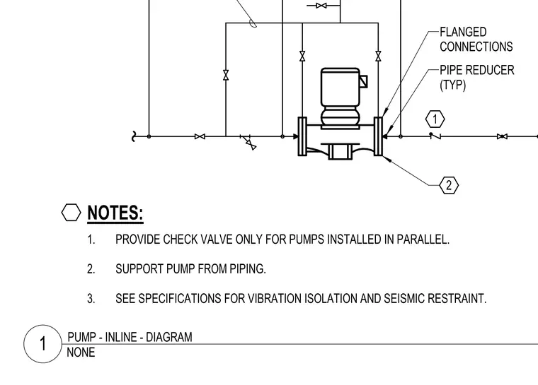
An inline pump is integrated into the piping layout with flanged connections and typical pipe reducers on either side. The assembly relies on piping support rather than independent floor mounts, with check valves required only for pumps installed in parallel configurations. Vibration isolation and seismic restraints must follow project specifications.
1. PROVIDE CHECK VALVE ONLY FOR PUMPS INSTALLED IN PARALLEL. 2. SUPPORT PUMP FROM PIPING. 3. SEE SPECIFICATIONS FOR VIBRATION ISOLATION AND SEISMIC RESTRAINT. NOTES: 2 1 1/4" TUBING FLANGED CONNECTIONS PIPE REDUCER (TYP) NONE 1 PUMP - INLINE - DIAGRAM
Members view this detail in full resolution, download the CAD files (SVG, PDF), and can adapt it in the built-in CAD editor — export DXF, DWG, or PDF.
Start membership