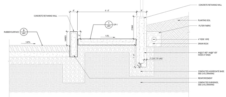
A reinforced concrete retaining wall retains planting soil on one side and bounds a sloped path finished with a rubber surface on the other. The wall is reinforced with number four bars spaced at twelve inches horizontally and six inches vertically with hooked ends, set with two inches of cover typically unless noted otherwise. A four-inch perforated pipe wrapped in filter fabric and surrounded by drain rock provides drainage behind the higher wall element. The subgrade and aggregate base beneath the assembly are constructed per the civil drawings, supporting the concrete path slab which slopes at one and five-tenths percent.
9 L601 RUBBER SURFACE 1.67% 1.5% VARIES 6" 6" 2' MAX 4' - 0" CONCRETE RETAINING WALL COMPACTED AGGREGATE BASE, SEE CIVIL DRAWING CIP-1 REINFORCEMENT 1 L601 COMPACTED SUBGRADE, SEE CIVIL DRAWING CONCRETE RETAINING WALL FILTER FABRIC 4" PERF. PIPE DRAIN ROCK PLANTING SOIL 1' - 6" CVR 3" 2" CVR TYP UNO #4@12" HEF #4@6" VEF HOOK AT ENDS 8"
Members view this detail in full resolution, download the CAD files (SVG, PDF), and can adapt it in the built-in CAD editor — export DXF, DWG, or PDF.
Start membership