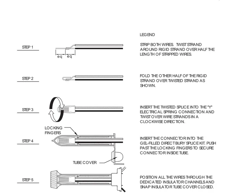
Strip both wires and twist one strand around the rigid strand over half the length of the stripped wires. Fold the remaining half of the rigid strand over the twisted strand. Insert the twisted splice into the electrical spring connection and twist clockwise. Insert the connector into the gel-filled direct bury splice kit past the locking fingers. Position all wires through the dedicated insulator channels and snap the tube cover closed.
LOCKING FINGERS STEP 4 STEP 5 STEP 2 STEP 3 STEP 1 eq POSITION ALL THE WIRES THROUGH THE DEDICATED INSULATOR CHANNELS AND SNAP INSULATOR TUBE COVER CLOSED. INSERT THE CONNECTOR INTO THE GEL-FILLED DIRECT BURY SPLICE KIT. PUSH PAST THE LOCKING FINGERS TO SECURE CONNECTOR INSIDE TUBE. TUBE COVER STRIP BOTH WIRES. TWIST STRAND AROUND RIGID STRAND OVER HALF THE LENGTH OF STRIPPED WIRES. INSERT THE TWISTED SPLICE INTO THE "Y" ELECTRICAL SPRING CONNECTION AND TWIST OVER WIRE STRANDS IN A CLOCKWISE DIRECTION. FOLD THE OTHER HALF OF THE RIGID STRAND OVER TWISTED STRAND AS SHOWN. eq LEGEND
Members view this detail in full resolution, download the CAD files (SVG, PDF), and can adapt it in the built-in CAD editor — export DXF, DWG, or PDF.
Start membership