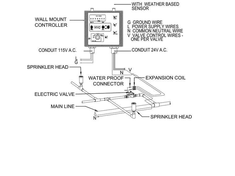
A wall-mounted controller connects to a weather-based sensor and receives power supply lines through a 115-volt alternating current conduit containing ground, power, and neutral wires. Valve control wires run from the controller through a 24-volt alternating current conduit to an electric valve assembly on the main irrigation line. Waterproof connectors and expansion coils link the control wires to the valve, while sprinkler heads connect directly to the lateral piping.
N V ONE PER VALVE CONDUIT 24V A.C. V VALVE CONTROL WIRES - N COMMON NEUTRAL WIRE L POWER SUPPLY WIRES G GROUND WIRE CONDUIT 115V A.C. WATER PROOF G L N WITH WEATHER BASED SENSOR SPRINKLER HEAD MAIN LINE EXPANSION COIL WATER PROOF CONNECTOR ELECTRIC VALVE SPRINKLER HEAD WALL MOUNT CONTROLLER
Members view this detail in full resolution, download the CAD files (SVG, PDF), and can adapt it in the built-in CAD editor — export DXF, DWG, or PDF.
Start membership