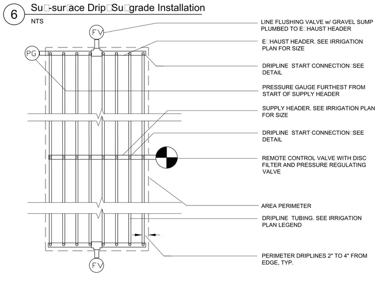
The sub-surface drip installation layout comprises supply and exhaust headers sized per the irrigation plan, connected to parallel dripline tubing spaced across the area perimeter. Perimeter driplines are positioned two to four inches from the edge. A remote control valve with a disc filter and pressure regulating valve feeds the system. A pressure gauge is installed at the location furthest from the start of the supply header. A line flushing valve with a gravel sump is plumbed directly to the exhaust header.
6 NTS Sub-surface Drip: Subgrade Installation AREA PERIMETER DRIPLINE TUBING. SEE IRRIGATION PLAN LEGEND REMOTE CONTROL VALVE WITH DISC FILTER AND PRESSURE REGULATING VALVE DRIPLINE START CONNECTION: SEE DETAIL DRIPLINE START CONNECTION: SEE DETAIL PERIMETER DRIPLINES 2" TO 4" FROM EDGE, TYP. LINE FLUSHING VALVE w/ GRAVEL SUMP PLUMBED TO EXHAUST HEADER PRESSURE GAUGE FURTHEST FROM START OF SUPPLY HEADER SUPPLY HEADER. SEE IRRIGATION PLAN FOR SIZE EXHAUST HEADER. SEE IRRIGATION PLAN FOR SIZE
Members view this detail in full resolution, download the CAD files (SVG, PDF), and can adapt it in the built-in CAD editor — export DXF, DWG, or PDF.
Start membership