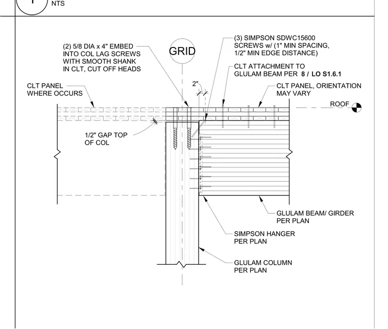
A glulam beam or girder connects to a glulam column per plan using a concealed Simpson hanger sized per plan. Cross-laminated timber panels bear on top of the assembly, with panel orientation varying as required and attachment detailed per plan. Two five-eighths-inch diameter by four-inch embedment lag screws with smooth shanks are installed vertically into the top of the column with cut-off heads. Three Simpson SDWC15600 screws secure the connection with a one-inch minimum spacing and half-inch minimum edge distance, maintaining a two-inch grid. A half-inch gap is provided at the top of the column below the cross-laminated timber panel.
ROOF GLULAM COLUMN PER PLAN GLULAM BEAM/ GIRDER PER PLAN CLT PANEL, ORIENTATION MAY VARY CLT PANEL WHERE OCCURS SIMPSON HANGER PER PLAN (3) SIMPSON SDWC15600 SCREWS w/ (1" MIN SPACING, 1/2" MIN EDGE DISTANCE) 2" GRID CLT ATTACHMENT TO GLULAM BEAM PER / 8 LO S1.6.1 1/2" GAP TOP OF COL (2) 5/8 DIA x 4" EMBED INTO COL LAG SCREWS WITH SMOOTH SHANK IN CLT, CUT OFF HEADS NTS 1
Members view this detail in full resolution, download the CAD files (SVG, PDF), and can adapt it in the built-in CAD editor — export DXF, DWG, or PDF.
Start membership