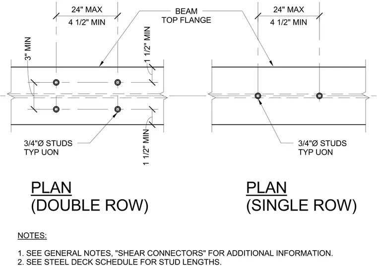
Plan layout requirements for shear connector studs welded to a steel beam top flange feature both single and double row configurations. The double row arrangement specifies three-quarter inch diameter studs typically used unless otherwise noted, with a minimum transverse edge distance of three inches and longitudinal spacing ranging from four and a half inches minimum to twenty-four inches maximum. The single row configuration maintains similar longitudinal spacing constraints with a one and a half inch minimum edge distance. Additional general notes direct the user to verify shear connector information and reference the steel deck schedule for required stud lengths.
PLAN (DOUBLE ROW) PLAN (SINGLE ROW) NOTES: 1. SEE GENERAL NOTES, "SHEAR CONNECTORS" FOR ADDITIONAL INFORMATION. 2. SEE STEEL DECK SCHEDULE FOR STUD LENGTHS. BEAM TOP FLANGE 3/4"Ø STUDS TYP UON 4 1/2" MIN 24" MAX 4 1/2" MIN 24" MAX 3/4"Ø STUDS TYP UON 1 1/2" MIN 1 1/2" MIN 3" MIN
Members view this detail in full resolution, download the CAD files (SVG, PDF), and can adapt it in the built-in CAD editor — export DXF, DWG, or PDF.
Start membership