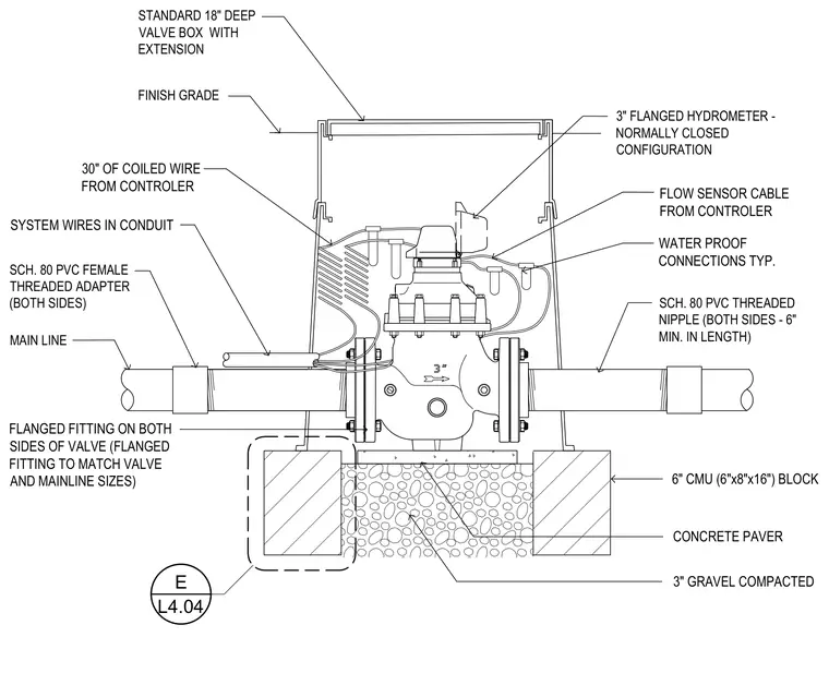
A three-inch flanged hydrometer in a normally closed configuration is housed within a standard eighteen-inch deep valve box with an extension, resting upon a compacted concrete paver and three inches of compacted gravel. The assembly connects to the main line via schedule eighty PVC threaded nipples at least six inches in length, schedule eighty PVC female threaded adapters on both sides, and flanged fittings matched to the valve and mainline sizes. System wires run in conduit with thirty inches of coiled wire from the controller, linking to the flow sensor cable through typical waterproof connections. The valve box is framed at its base by six-inch concrete masonry units measuring six by eight by sixteen inches below finish grade.
MAIN LINE SCH. 80 PVC THREADED NIPPLE (BOTH SIDES - 6" MIN. IN LENGTH) SCH. 80 PVC FEMALE THREADED ADAPTER (BOTH SIDES) FLANGED FITTING ON BOTH SIDES OF VALVE (FLANGED FITTING TO MATCH VALVE AND MAINLINE SIZES) STANDARD 18" DEEP VALVE BOX WITH EXTENSION 3" FLANGED HYDROMETER - NORMALLY CLOSED CONFIGURATION FINISH GRADE 6" CMU (6"x8"x16") BLOCK SYSTEM WIRES IN CONDUIT 30" OF COILED WIRE FROM CONTROLER FLOW SENSOR CABLE FROM CONTROLER WATER PROOF CONNECTIONS TYP. 3" GRAVEL COMPACTED CONCRETE PAVER E L4.04
Members view this detail in full resolution, download the CAD files (SVG, PDF), and can adapt it in the built-in CAD editor — export DXF, DWG, or PDF.
Start membership