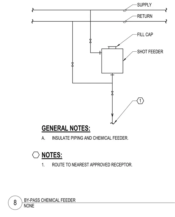
This diagram details the plumbing arrangement for a by-pass chemical shot feeder connected to supply and return lines. The system includes isolation valves on the piping paths, a fill cap on the shot feeder, and insulated piping throughout. Drainage or discharge is routed to the nearest approved receptor per note requirements.
FILL CAP SHOT FEEDER A. INSULATE PIPING AND CHEMICAL FEEDER. GENERAL NOTES: 1. ROUTE TO NEAREST APPROVED RECEPTOR. NOTES: RETURN SUPPLY 1 NONE 8 BY-PASS CHEMICAL FEEDER
Members view this detail in full resolution, download the CAD files (SVG, PDF), and can adapt it in the built-in CAD editor — export DXF, DWG, or PDF.
Start membership