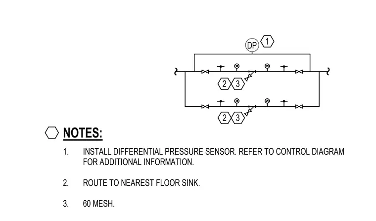
The duplex strainer assembly includes valves, pressure gauges, and a differential pressure sensor tied to the control diagram. A sixty mesh filter is installed within the strainer body. Piping drainage routes directly to the nearest floor sink.
1. INSTALL DIFFERENTIAL PRESSURE SENSOR. REFER TO CONTROL DIAGRAM FOR ADDITIONAL INFORMATION. 2. ROUTE TO NEAREST FLOOR SINK. 3. 60 MESH. NOTES: 3 3 1 DP 2 2
Members view this detail in full resolution, download the CAD files (SVG, PDF), and can adapt it in the built-in CAD editor — export DXF, DWG, or PDF.
Start membership