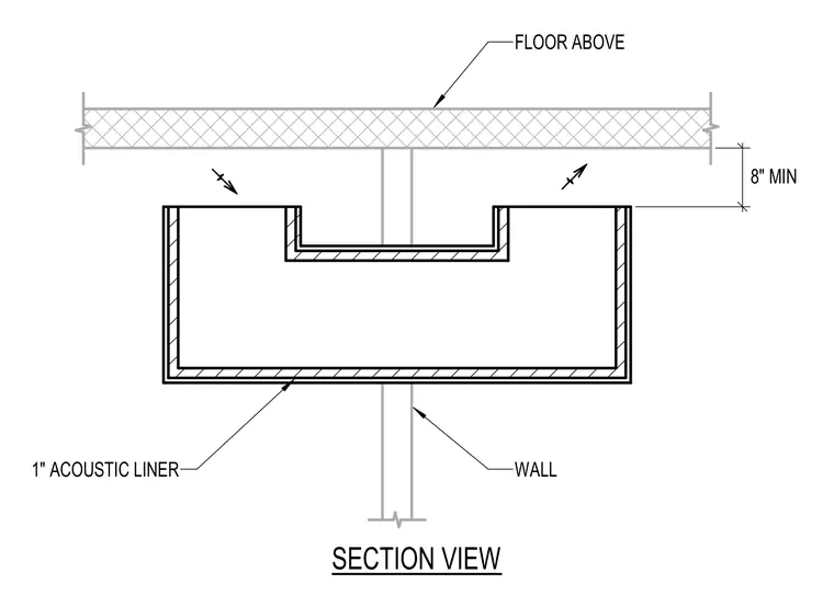
An acoustic-lined duct is positioned below the floor above, maintaining a minimum clearance of eight inches from the top of the duct to the underside of the floor slab. The duct features a one-inch acoustic liner on its interior surfaces and connects to a vertical wall below.
Members view this detail in full resolution, download the CAD files (SVG, PDF), and can adapt it in the built-in CAD editor — export DXF, DWG, or PDF.
Start membership