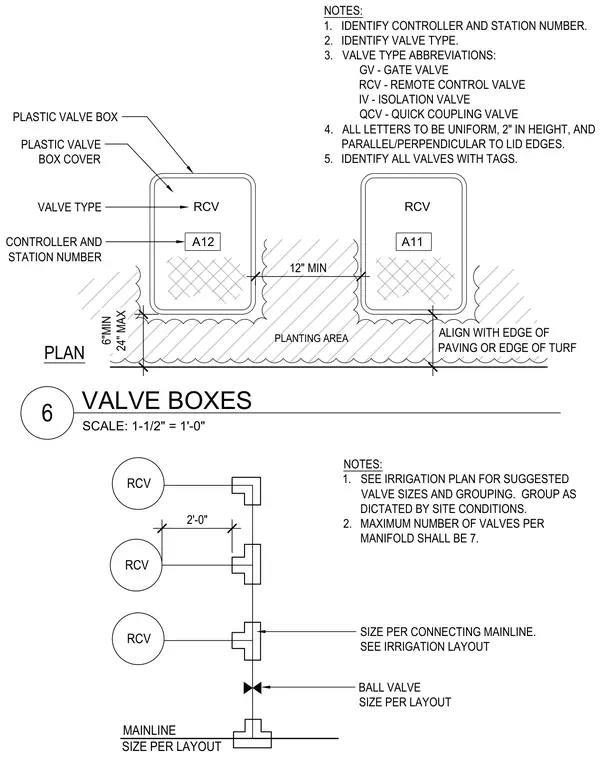
This installation detail shows plastic valve boxes and remote control valves positioned adjacent to paving edges or turf in a planting area. Plastic valve box covers are marked with the valve type and controller station number using two-inch high lettering parallel to the lid edges. Manifolds connect remote control valves to the mainline with a maximum of seven valves per manifold and a two-foot spacing between branches. Ball valves and mainline sizing are indicated per the irrigation layout.
SCALE: 1-1/2" = 1'-0" VALVE BOXES A12 RCV PLANTING AREA A11 RCV NOTES: 1. IDENTIFY CONTROLLER AND STATION NUMBER. 2. IDENTIFY VALVE TYPE. 3. VALVE TYPE ABBREVIATIONS: GV - GATE VALVE RCV - REMOTE CONTROL VALVE IV - ISOLATION VALVE QCV - QUICK COUPLING VALVE 4. ALL LETTERS TO BE UNIFORM, 2" IN HEIGHT, AND PARALLEL/PERPENDICULAR TO LID EDGE S. 5. IDENTIFY ALL VALVES WITH TAGS. 6"MIN 24" MAX 12" MIN PLASTIC VALVE BOX CONTROLLER AND STATION NUMBER VALVE TYPE PLASTIC VALVE BOX COVER ALIGN WITH EDGE OF PAVING OR EDGE OF TURF PLAN RCV MAINLINE NOTES: 1. SEE IRRIGATION PLAN FOR SUGGESTED VALVE SIZES AND GROUPING. GROUP AS DICTATED BY SITE CONDITIONS. 2. MAXIMUM NUMBER OF VALVES PER MANIFOLD SHALL BE 7. SIZE PER LAYOUT 2'-0" SIZE PER CONNECTING MAINLINE. SEE IRRIGATION LAYOUT BALL VALVE SIZE PER LAYOUT RCV RCV 6
Members view this detail in full resolution, download the CAD files (SVG, PDF), and can adapt it in the built-in CAD editor — export DXF, DWG, or PDF.
Start membership