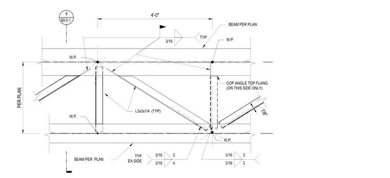
A steel truss connection features members sized per plan. The assembly incorporates L3x3x1/4 typical angles connected with three-sixteenths inch fillet welds typically on each side. A coped angle is specified at the top flange on this side only. Work points define the geometry with a four foot spacing along the chord. Weld symbols indicate three-sixteenths inch welds distributed across the connection nodes.
4'-0" PER PLAN W.P. 8 S8.0.1 BEAM PER PLAN 3/16 3 3/16 3 3/16 4 3/16 2 TYP EA SIDE BEAM PER PLAN L3x3x1/4 (TYP) W.P. 7/8" W.P. W.P. COP ANGLE TOP FLANG (ON THIS SIDE ONLY) 3/16 TYP 4'-0" PER PLAN W.P. 8 S8.0.1 BEAM PER PLAN 3/16 3 3/16 3 3/16 4 3/16 2 TYP EA SIDE BEAM PER PLAN L3x3x1/4 (TYP) W.P. 7/8" W.P. W.P. COP ANGLE TOP FLANG (ON THIS SIDE ONLY) 3/16 TYP
Members view this detail in full resolution, download the CAD files (SVG, PDF), and can adapt it in the built-in CAD editor — export DXF, DWG, or PDF.
Start membership