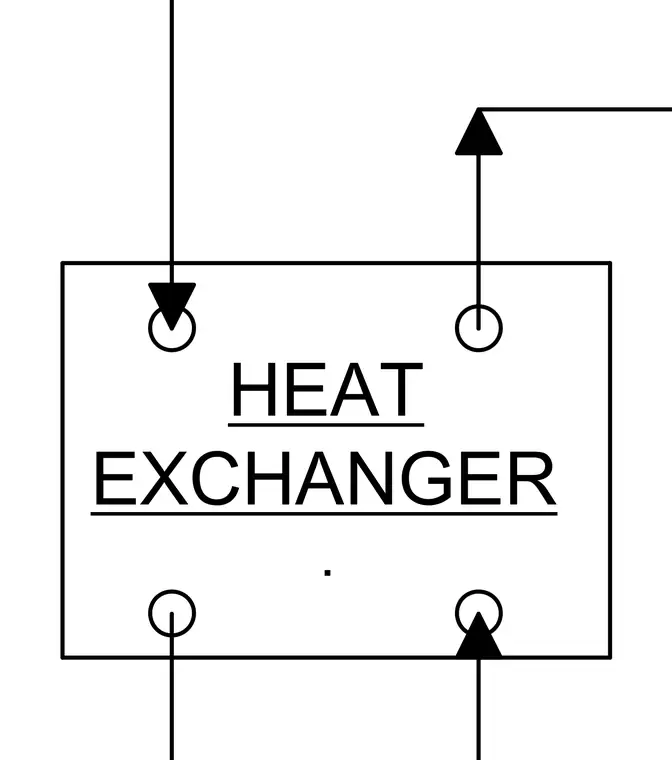
This schematic diagram outlines a heat exchanger unit featuring four primary fluid connection points configured with incoming and outgoing flow arrows. The rectangular enclosure clearly designates the heat exchanger unit for mechanical and plumbing coordination.
HEAT EXCHANGER .
Members view this detail in full resolution, download the CAD files (SVG, PDF), and can adapt it in the built-in CAD editor — export DXF, DWG, or PDF.
Start membership