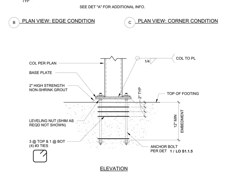
The gravity column as sized per plan connects to a steel base plate via a quarter-inch fillet weld around the column profile. The base plate rests on a two-inch layer of high-strength non-shrink grout above the top of the concrete footing. Anchor bolts are sized per detail one on sheet LO S1.1.5 with a twelve-inch minimum embedment into the concrete footing. Leveling nuts and optional shims are provided below the base plate. Four number-three ties are placed within the footing concrete around the anchor bolts, arranged with three at the top and one at the bottom.
ELEVATION COL PER PLAN 3 @ TOP & 1 @ BOT (4) #3 TIES BASE PLATE 2" HIGH STRENGTH NON-SHRINK GROUT EMBEDMENT 12" MIN 1/4 COL TO PL ANCHOR BOLT PER DET TYP TYP PLAN VIEW: CORNER CONDITION C PLAN VIEW: EDGE CONDITION B SEE DET "A" FOR ADDITIONAL INFO. 2" TYP TOP OF FOOTING / 1 LO S1.1.5 LEVELING NUT (SHIM AS REQD NOT SHOWN)
Members view this detail in full resolution, download the CAD files (SVG, PDF), and can adapt it in the built-in CAD editor — export DXF, DWG, or PDF.
Start membership