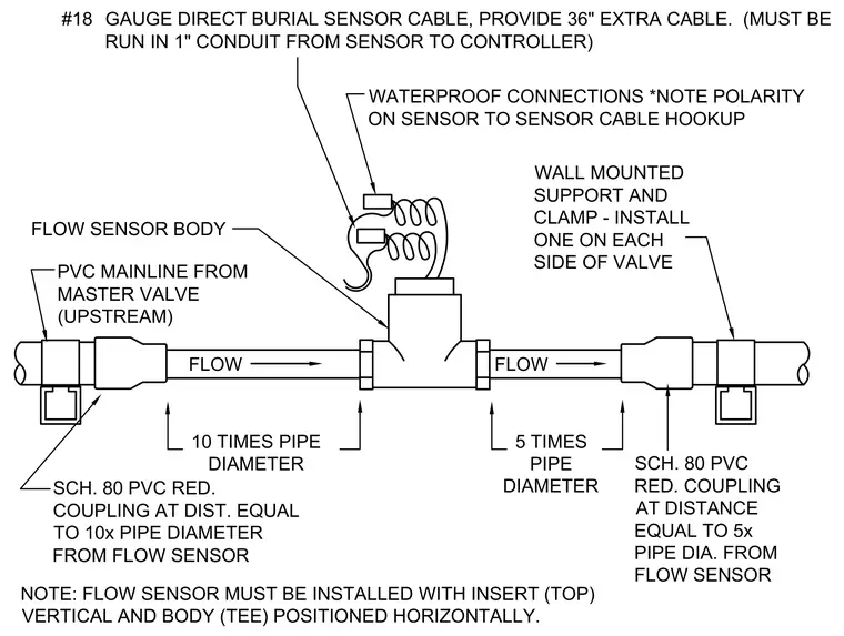
A PVC flow sensor body connects inline to a PVC mainline from the upstream master valve, maintaining a straight pipe run of ten times the pipe diameter upstream and five times the pipe diameter downstream. Schedule 80 PVC reducer couplings locate at these specific distances on each side of the sensor. Wall-mounted supports and clamps secure the pipe on each side of the valve assembly. The flow sensor requires installation with the insert vertical and the tee body positioned horizontally. Waterproof connections join the number eighteen gauge direct burial sensor cable, which includes thirty-six inches of extra cable run in a one-inch conduit to the controller while observing correct polarity.
FLOW FLOW WALL MOUNTED SUPPORT AND CLAMP - INSTALL ONE ON EACH SIDE OF VALVE GAUGE DIRECT BURIAL SENSOR CABLE, PROVIDE 36" EXTRA CABLE. (MUST BE RUN IN 1" CONDUIT FROM SENSOR TO CONTROLLER) WATERPROOF CONNECTIONS *NOTE POLARITY ON SENSOR TO SENSOR CABLE HOOKUP FLOW SENSOR BODY PVC MAINLINE FROM MASTER VALVE (UPSTREAM) 10 TIMES PIPE DIAMETER SCH. 80 PVC RED. COUPLING AT DIST. EQUAL TO 10x PIPE DIAMETER FROM FLOW SENSOR 5 TIMES PIPE DIAMETER SCH. 80 PVC RED. COUPLING AT DISTANCE EQUAL TO 5x PIPE DIA. FROM FLOW SENSOR NOTE: FLOW SENSOR MUST BE INSTALLED WITH INSERT (TOP) VERTICAL AND BODY (TEE) POSITIONED HORIZONTALLY. #18
Members view this detail in full resolution, download the CAD files (SVG, PDF), and can adapt it in the built-in CAD editor — export DXF, DWG, or PDF.
Start membership