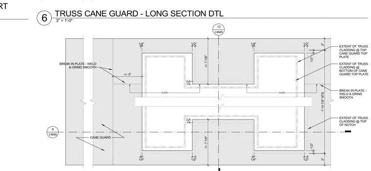
A steel truss cane guard assembly features plate breaks that are welded and ground smooth. The metal plate configurations establish specific alignment and clearances relative to the truss cladding extents at both the top and bottom top plates and notch locations. Dimensioned gaps include half-inch and quarter-inch spacings alongside approximate five-inch and seven-and-seven-eighths-inch offsets. The layout coordinates the cane guard profile with the surrounding structural truss members.
1'-10 7/8" NTS EXTENT OF TRUSS CLADDING @ TOP OF NOTCH EXTENT OF TRUSS CLADDING @ TOP CANE GUARD TOP PLATE EXTENT OF TRUSS CLADDING @ BOTTOM OF CANE GUARD TOP PLATE CANE GUARD BREAK IN PLATE - WELD & GRIND SMOOTH 1/2" 1/4" 1/2" 1/4" 1/2" 1/4" 1/2" 1/2" 1/2" 1/4" 2" 1/2" 2" 1/2" +/- 5" +/- 7 7/8" ALIGN ALIGN BREAK IN PLATE - WELD & GRIND SMOOTH +/- 7 7/8" 6 I-M45 10 I-M45 TRUSS CANE GUARD - SHORT 3" = 1'-0" 6 TRUSS CANE GUARD - LONG SECTION DTL
Members view this detail in full resolution, download the CAD files (SVG, PDF), and can adapt it in the built-in CAD editor — export DXF, DWG, or PDF.
Start membership