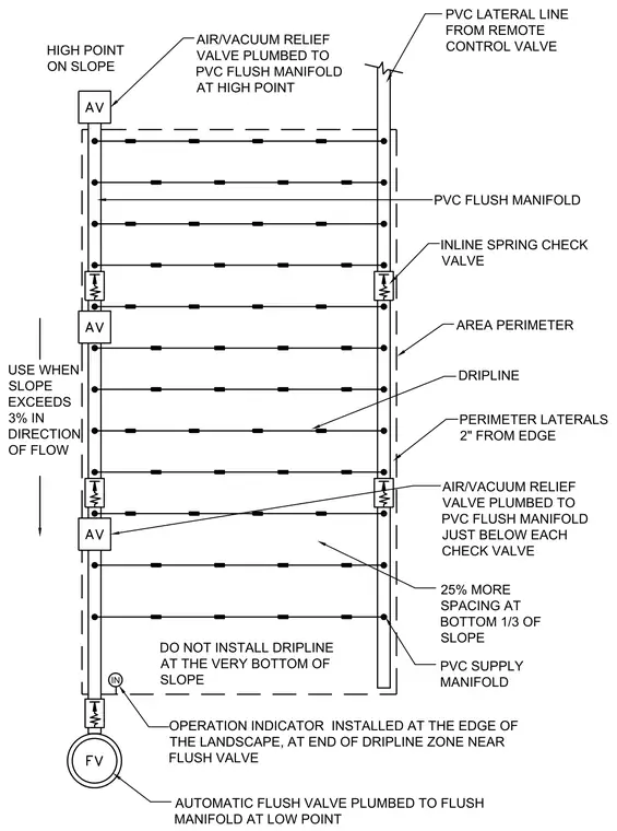
An inline drip irrigation layout for sloped terrain incorporates a PVC supply manifold feeding lateral lines equipped with driplines. Inline spring check valves and air or vacuum relief valves plumb to a PVC flush manifold to manage pressure and drainage across slopes exceeding three percent. Perimeter laterals run two inches from the area edge, with increased spacing applied at the bottom third of the slope and driplines omitted from the very bottom. An automatic flush valve sits at the low point, accompanied by an operation indicator installed near the edge of the landscape at the end of the dripline zone.
PVC FLUSH MANIFOLD AREA PERIMETER DRIPLINE AIR/VACUUM RELIEF VALVE PLUMBED TO PVC FLUSH MANIFOLD JUST BELOW EACH CHECK VALVE PVC LATERAL LINE FROM REMOTE CONTROL VALVE INLINE SPRING CHECK VALVE PERIMETER LATERALS 2" FROM EDGE AUTOMATIC FLUSH VALVE PLUMBED TO FLUSH MANIFOLD AT LOW POINT HIGH POINT ON SLOPE USE WHEN SLOPE EXCEEDS 3% IN DIRECTION OF FLOW AIR/VACUUM RELIEF VALVE PLUMBED TO PVC FLUSH MANIFOLD AT HIGH POINT PVC SUPPLY MANIFOLD DO NOT INSTALL DRIPLINE AT THE VERY BOTTOM OF SLOPE 25% MORE SPACING AT BOTTOM 1/3 OF SLOPE IN OPERATION INDICATOR INSTALLED AT THE EDGE OF THE LANDSCAPE, AT END OF DRIPLINE ZONE NEAR FLUSH VALVE
Members view this detail in full resolution, download the CAD files (SVG, PDF), and can adapt it in the built-in CAD editor — export DXF, DWG, or PDF.
Start membership