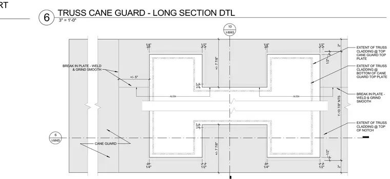
A structural steel cane guard assembly is integrated with truss cladding. Plate breaks are specified with welded and ground smooth joints. Dimensional clearances include half-inch and quarter-inch offsets, two-inch spacings, and alignment markers with plus or minus five-inch and seven-and-seven-eighths-inch tolerances. Extents for truss cladding are demarcated at the top of the notch, bottom of the cane guard top plate, and top of the cane guard top plate.
1'-10 7/8" NTS EXTENT OF TRUSS CLADDING @ TOP OF NOTCH EXTENT OF TRUSS CLADDING @ TOP CANE GUARD TOP PLATE EXTENT OF TRUSS CLADDING @ BOTTOM OF CANE GUARD TOP PLATE CANE GUARD BREAK IN PLATE - WELD & GRIND SMOOTH 1/2" 1/4" 1/2" 1/4" 1/2" 1/4" 1/2" 1/2" 1/2" 1/4" 2" 1/2" 2" 1/2" +/- 5" +/- 7 7/8" ALIGN ALIGN BREAK IN PLATE - WELD & GRIND SMOOTH +/- 7 7/8" 6 I-M45 10 I-M45 TRUSS CANE GUARD - SHORT 3" = 1'-0" 6 TRUSS CANE GUARD - LONG SECTION DTL
Members view this detail in full resolution, download the CAD files (SVG, PDF), and can adapt it in the built-in CAD editor — export DXF, DWG, or PDF.
Start membership