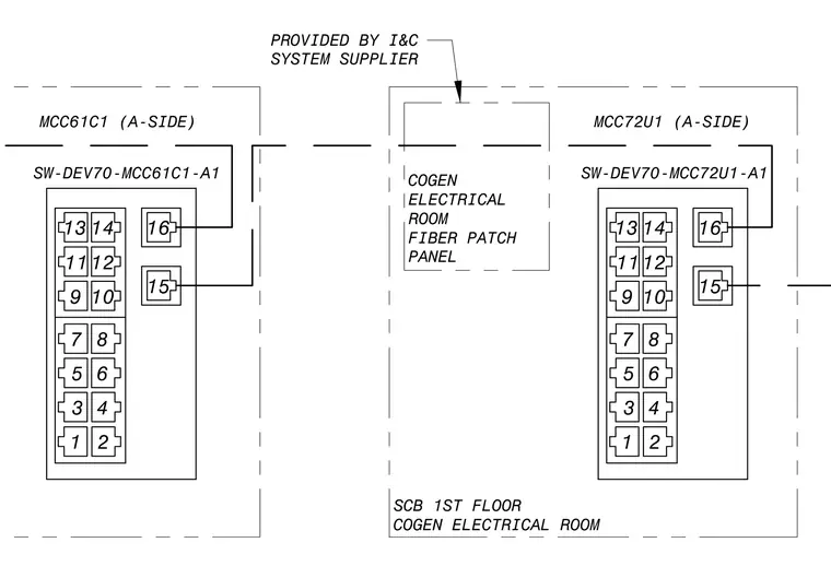
This diagram details the electrical connections between motor control centers MCC61C1 and MCC72U1 on the A-side alongside a cogen electrical room fiber patch panel provided by the instrumentation and controls system supplier. Labeled terminal blocks numbered one through sixteen connect via designated data cables such as SW-DEV70-MCC61C1-A1 and SW-DEV70-MCC72U1-A1. The layout establishes the signal routing between the specified MCC units and the central patch panel located on the first floor.
MCC61C1 (A-SIDE) 13 11 9 7 5 3 1 14 12 10 8 6 4 2 16 15 SW-DEV70-MCC61C1-A1 MCC72U1 (A-SIDE) 13 11 9 7 5 3 1 14 12 10 8 6 4 2 16 15 SW-DEV70-MCC72U1-A1 SCB 1ST FLOOR COGEN ELECTRICAL ROOM COGEN ELECTRICAL ROOM FIBER PATCH PANEL PROVIDED BY I&C SYSTEM SUPPLIER
Members view this detail in full resolution, download the CAD files (SVG, PDF), and can adapt it in the built-in CAD editor — export DXF, DWG, or PDF.
Start membership