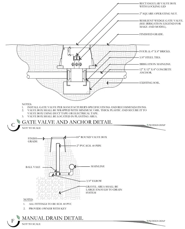
A resilient wedge gate valve equipped with a two-inch square operating nut is positioned inside a rectangular valve box with a locking lid. The valve connects to an irrigation mainline supported by a twelve-by-twelve-by-eight-inch concrete anchor with three-eighths-inch steel ties and four four-by-eight-inch bricks. The valve box sits in a planting area with a six-inch minimum clearance below finished grade and is wrapped in three-mil thick plastic secured with duct tape or electrical tape. A secondary manual drain detail includes a ten-inch round valve box with a two-inch polyvinyl chloride schedule forty pipe, ball valve, mainline connection, three-quarter-inch elbow, and surrounding gravel drainage area.
NOTES: 1. ALL FITTINGS TO BE SCH. 80 PVC 2. PROVIDE OWNER WITH KEY PKJ DESIGN GROUP GATE VALVE AND ANCHOR DETAIL NOT TO SCALE C NOTES: 1. INSTALL GATE VALVE PER MANUFACTURER'S SPECIFICATIONS AND RECOMMENDATIONS. 2. VALVE BOX SHALL BE WRAPPED WITH MINIMUM 3 MIL. THICK PLASTIC AND SECURE IT TO VALVE BOX USING DUCT TAPE OR ELECTRICAL TAPE. 3. VALVE BOX SHALL BE LOCATED IN PLANTING AREA. PKJ DESIGN GROUP MANUAL DRAIN DETAIL NOT TO SCALE F GRAVEL AREA SHALL BE LARGE ENOUGH TO DRAIN SYSTEM 3/4" ELBOW MAINLINE BALL VALE 2" PVC SCH. 40 PIPE 10" ROUND VALVE BOX FINISH GRADE RECTANGULAR VALVE BOX WITH LOCKING LID 2" SQUARE OPERATING NUT. RESILIENT WEDGE GATE VALVE. (SEE IRRIGATION LEGEND FOR MAKE AND MODEL). FINISHED GRADE. FOUR (4) 4" X 8" BRICKS. 3/8" STEEL TIES. IRRIGATION MAINLINE. 12" X 12" X 8" CONCRETE ANCHOR. EXISTING SOIL. 6" MIN. c c cn o O o O o O o o O o O o O o i z o O o O o O o fl oO &OoO o/C C 7^ ----------- 7^ I I- • L-n-r 5 < i ■ I i I © CXJ 0 0
Members view this detail in full resolution, download the CAD files (SVG, PDF), and can adapt it in the built-in CAD editor — export DXF, DWG, or PDF.
Start membership