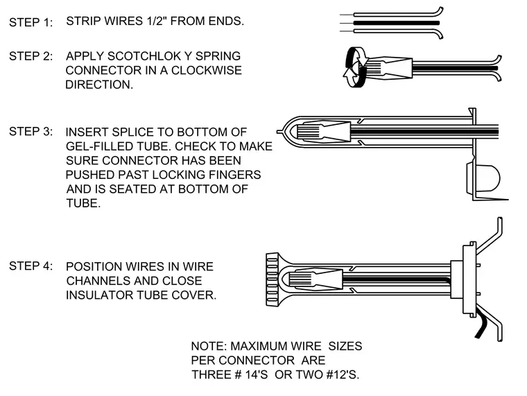
Step one requires stripping wires one-half inch from their ends. Step two involves applying a Scotchlok Y spring connector in a clockwise direction. Step three inserts the splice to the bottom of a gel-filled tube, checking that the connector passes past locking fingers and seats properly. Step four positions the wires in wire channels and closes the insulator tube cover. Maximum wire sizes per connector are limited to three number fourteen wires or two number twelve wires.
POSITION WIRES IN WIRE CHANNELS AND CLOSE INSULATOR TUBE COVER. INSERT SPLICE TO BOTTOM OF GEL-FILLED TUBE. CHECK TO MAKE SURE CONNECTOR HAS BEEN PUSHED PAST LOCKING FINGERS AND IS SEATED AT BOTTOM OF TUBE. APPLY SCOTCHLOK Y SPRING CONNECTOR IN A CLOCKWISE DIRECTION. STRIP WIRES 1/2" FROM ENDS. STEP 4: STEP 3: STEP 2: STEP 1: NOTE: MAXIMUM WIRE SIZES PER CONNECTOR ARE THREE # 14'S OR TWO #12'S.
Members view this detail in full resolution, download the CAD files (SVG, PDF), and can adapt it in the built-in CAD editor — export DXF, DWG, or PDF.
Start membership