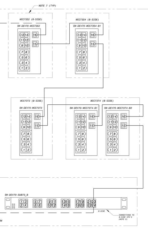
This diagram details the terminal connections and wiring arrangements between electrical equipment within the SCB electrical room. It maps out connections to B-side variable frequency drives and motor control centers including units MCC73S2, MCC73S4, MCC73T2, and MCC73T4. Terminal blocks and individual numbered pins are explicitly designated for routing control and power signals. System interconnections link to subpanel SW-DEV70-SUB73_B per designated installation notes.
B-SIDE 13 11 9 7 5 3 1 14 12 10 8 6 4 2 16 15 13 11 9 7 5 3 1 14 12 10 8 6 4 2 16 15 MCC73T4 (B-SIDE) MCC73S4 (B-SIDE) SW-DEV70-MCC73S4-B1 SW-DEV70-SUB73_B CONNECTIONS TO B-SIDE VFD'S (NOTE 2) 1 3 2 4 6 8 1012 5 7 9 11 1416 1315 1820 1719 2224 2123 SW-DEV70-MCC73T4-B1 SW-DEV70-MCC73T4-B2 SCB ELECTRICAL ROOM SW-DEV70-MCC73S2 MCC73S2 (B-SIDE) 13 11 9 7 5 3 1 14 12 10 8 6 4 2 16 15 MCC73T2 (B-SIDE) SW-DEV70-MCC73T2 13 11 9 7 5 3 1 14 12 10 8 6 4 2 16 15 13 11 9 7 5 3 1 14 12 10 8 6 4 2 16 15 NOTE 7 (TYP)
Members view this detail in full resolution, download the CAD files (SVG, PDF), and can adapt it in the built-in CAD editor — export DXF, DWG, or PDF.
Start membership