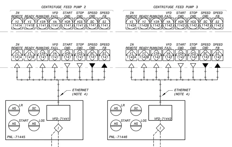
Control diagram for Centrifuge Feed Pump 2 and Centrifuge Feed Pump 3 illustrating variable frequency drive interlocks and instrumentation signals. Panel connections include VFD-71441 and VFD-71442 linked via Ethernet communication per note 4, alongside local-remote switches and start-stop commands. Status points monitor remote operation readiness, running state, fault conditions, and speed feedback variables through designated tag numbers.
YA 1141 FAIL VFD YA 1141 FAIL VFD SI 1141 FB SPEED SI 1141 FB SPEED SC 1141 CMD SPEED SC 1141 CMD SPEED CENTRIFUGE FEED PUMP 2 YCR 1141 CMD START YCR 1141 CMD START YCS 1141 CMD STOP YCS 1141 CMD STOP YIR 1141 RUNNING YIR 1141 RUNNING YI 1141B READY YI 1141B READY ETHERNET (NOTE 4) YA 1142 FAIL VFD YA 1142 FAIL VFD SI 1142 FB SPEED SI 1142 FB SPEED SC 1142 CMD SPEED SC 1142 CMD SPEED YCR 1142 CMD START YCR 1142 CMD START YCS 1142 CMD STOP YCS 1142 CMD STOP YIR 1142 RUNNING YIR 1142 RUNNING YI 1142B READY YI 1142B READY CENTRIFUGE FEED PUMP 3 I VFD-71442 PNL-71446 HS LR SC HS START HS LOS ETHERNET (NOTE 4) I VFD-71441 PNL-71445 HS LR SC HS START HS LOS YI 1141A REMOTE IN YI 1141A REMOTE IN YI 1142A REMOTE IN YI 1142A REMOTE IN
Members view this detail in full resolution, download the CAD files (SVG, PDF), and can adapt it in the built-in CAD editor — export DXF, DWG, or PDF.
Start membership