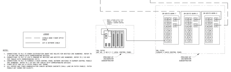
This diagram details the control and network connections for the Furnace 2 main control panel and associated burner control panels. The local control panel houses a Moxa ioTHINX-4510-T remote I/O module typical for forty furnace burner control panels provided by the incinerator subcontractor. Communication between cabinets utilizes single-mode fiber optic cables and category 6 network cables terminating at numbered patch panels and network switches. All copper and fiber communication cables between cabinets land on patch panels, which are referenced to sheet I-00-606 for corresponding tables and device numbers.
NOTES: 1. CONNECTIONS TO PLC 72 POWER DISTRIBUTION SMART MCC RELAYS FOR MCC73S2 ARE NUMBERED. REFER TO I-00-606 FOR TABLES WITH CORRESPONDING DEVICES. 2. CONNECTIONS TO PLC 72 VFD'S POWERED BY MCC73S2 AND MCC73T2 ARE NUMBERED. REFER TO I-00-606 FOR TABLES WITH CORRESPONDING VFD'S. 3. CONNECTIONS TO PLC 72 FURNACE 2 MAIN CONTROL PANEL NETWORK SWITCHES TO BURNER CONTROL PANELS ARE NUMBERED. REFER TO I-00-606 FOR TABLES WITH CORRESPONDING DEVICES. 4. FIBER OPTIC AND CAT-6 PATCH PANELS NOT SHOWN. 5. ALL COPPER AND FIBER COMMUNICATION CABLES BETWEEN CABINETS SHALL LAND ON PATCH PANELS. PATCH PANELS NOT SHOWN FOR CLARITY. LEGEND SINGLE-MODE FIBER OPTIC CABLE CAT-6 NETWORK CABLE 13 11 9 7 5 3 1 14 12 10 8 6 4 2 16 15 13 11 9 7 5 3 1 14 12 10 8 6 4 2 16 15 13 11 9 7 5 3 1 14 12 10 8 6 4 2 16 15 SW-DEV72-BURN-1 SW-DEV72-BURN-3 SW-DEV72-BURN-2 PNL-74764 FURNACE 2 MAIN CONTROL PANEL PNL-76720 MHF NO. 2 AB 2-1-1 LOCAL CONTROL PANEL MOXA ioTHINX-4510-T RIO MODULE. TYPICAL FOR 40 FURNACE 2 BURNER CONTROL PANELS. 45MR- 2606T 45MR- 3800T 45MR- 4420T PROVIDED BY INCINERATOR SUBCONTRACTOR PROVIDED BY INCINERATOR SUBCONTRACTOR
Members view this detail in full resolution, download the CAD files (SVG, PDF), and can adapt it in the built-in CAD editor — export DXF, DWG, or PDF.
Start membership