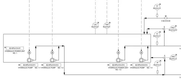
This piping and instrumentation diagram details the hydraulic power unit no. 1 with four integrated hydraulic pumps numbered 82-HPU-514-011 through 82-HPU-514-014. The system includes level switch low (LSL) 82-514-01 and temperature switch high (TSH) 82-514-01 for monitoring reservoir conditions. Pressure indicators (PI) and pressure relief valves (PRV) are arranged along the discharge lines to monitor and regulate system pressure.
V-82-514-01 V-82-514-04 LSL TSH PI PRV 82-514-012 PI 82-HPU-514-013 HYDRAULIC POWER UNIT NO. 1-3 82-HPU-514-014 HYDRAULIC PUMP NO. 1-4 PRV PI 82-HPU-514-011 HYDRAULIC PUMP NO. 1-1 82-HPU-514-012 HYDRAULIC PUMP NO. 1-2 V-82-514-06 82-HPU-514-01 HYDRAULIC POWER UNIT NO. 1
Members view this detail in full resolution, download the CAD files (SVG, PDF), and can adapt it in the built-in CAD editor — export DXF, DWG, or PDF.
Start membership