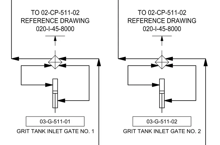
Control diagram for the grit tank inlet gate showing signal and reference routing to reference drawing 020-I-45-8000 and connection 02-CP-511-02. The schematic details signal routing paths and system interlocks associated with grit tank inlet gate number two.
03-G-511-01 GRIT TANK INLET GATE NO. 1 03-G-511-02 GRIT TANK INLET GATE NO. 2
Members view this detail in full resolution, download the CAD files (SVG, PDF), and can adapt it in the built-in CAD editor — export DXF, DWG, or PDF.
Start membership