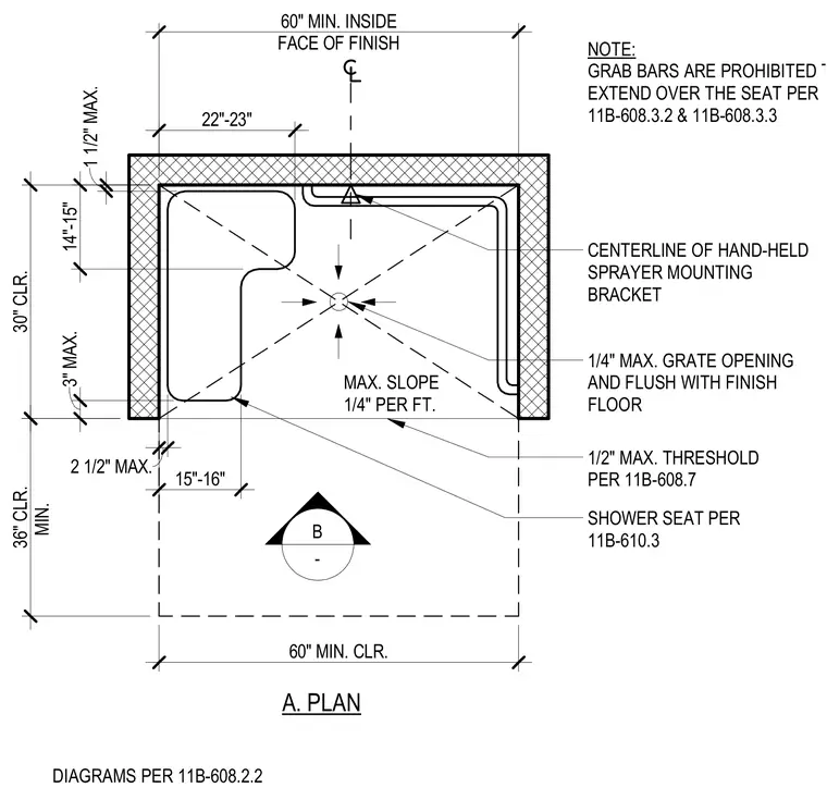
This roll-in type shower compartment plan details accessibility clearances and fixture locations in compliance with accessibility standards. The layout maintains a minimum sixty-inch inside face of finish width, a thirty-inch clear depth, and a thirty-six-inch minimum clear approach width outside the threshold. The floor features a maximum slope of one-quarter inch per foot toward a central floor drain with a grate opening of one-quarter inch maximum, flush with the finish floor. A shower seat is positioned along one side wall with specific mounting dimensions ranging from twenty-two to twenty-three inches to the centerline and seat clearances located two and one-half inches maximum from the threshold. A one-half-inch maximum threshold transitions into the compartment, and grab bars are prohibited from extending over the seat.
FACE OF FINISH 60" MIN. INSIDE 30" CLR. MIN. 36" CLR. 60" MIN. CLR. CENTERLINE OF HAND-HELD SPRAYER MOUNTING BRACKET 1/2" MAX. THRESHOLD PER 11B-608.7 SHOWER SEAT PER 11B-610.3 A. PLAN 22"-23" 14"-15" 15"-16" 3" MAX. 2 1/2" MAX. 1 1/2" MAX. MAX. SLOPE 1/4" PER FT. 1/4" MAX. GRATE OPENING AND FLUSH WITH FINISH FLOOR NOTE: GRAB BARS ARE PROHIBITED TO EXTEND OVER THE SEAT PER 11B-608.3.2 & 11B-608.3.3 B - DIAGRAMS PER 11B-608.2.2
Members view this detail in full resolution, download the CAD files (SVG, PDF), and can adapt it in the built-in CAD editor — export DXF, DWG, or PDF.
Start membership