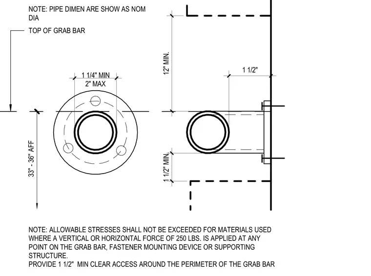
Grab bar mounting assembly showing height requirements between thirty-three and thirty-six inches above finished floor with a one-and-one-quarter-inch minimum to two-inch maximum diameter range. The mounting flange includes fastener holes and maintains a one-and-one-half-inch minimum clearance around the perimeter. Allowable stresses must not be exceeded for materials used where a vertical or horizontal force of two hundred fifty pounds is applied at any point on the grab bar, fastener mounting device, or supporting structure. Pipe dimensions are shown as nominal diameter to the top of the grab bar.
33" - 36" AFF 1 1/4" MIN 2" MAX 1 1/2" NOTE: PIPE DIMEN ARE SHOW AS NOM DIA TOP OF GRAB BAR NOTE: ALLOWABLE STRESSES SHALL NOT BE EXCEEDED FOR MATERIALS USED WHERE A VERTICAL OR HORIZONTAL FORCE OF 250 LBS. IS APPLIED AT ANY POINT ON THE GRAB BAR, FASTENER MOUNTING DEVICE OR SUPPORTING STRUCTURE. PROVIDE 1 1/2" MIN CLEAR ACCESS AROUND THE PERIMETER OF THE GRAB BAR 1 1/2" MIN. 12" MIN.
Members view this detail in full resolution, download the CAD files (SVG, PDF), and can adapt it in the built-in CAD editor — export DXF, DWG, or PDF.
Start membership