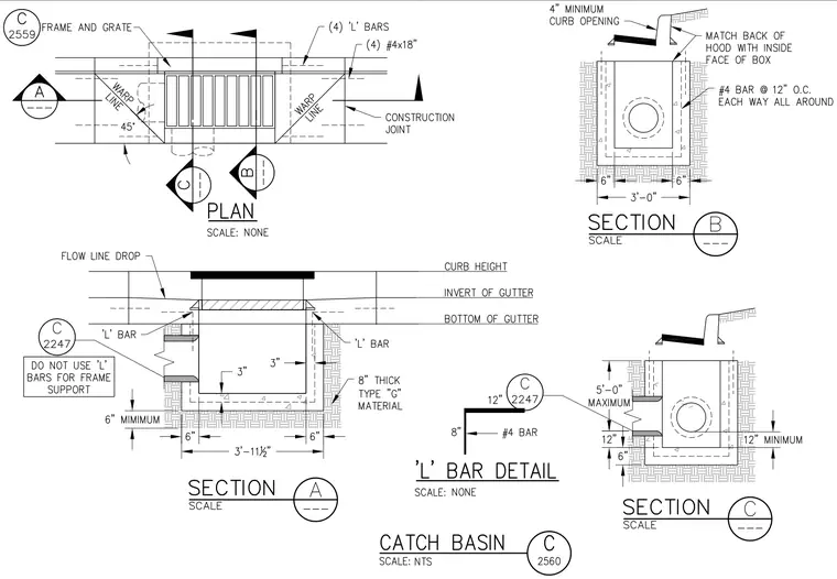
This civil engineering drawing details a standard catch basin assembly, including a plan view, multiple cross-sections, and an L-bar reinforcement detail. The concrete structure features eight-inch thick Type G material walls supported on a prepared sub-base with six-inch minimum clearance. Reinforcement includes number four bars at twelve inches on center each way all around and four L-bars specified around the perimeter. The top assembly incorporates a frame and grate, a four-inch minimum curb opening matching the back of the hood with the inside face of the box, and designated flow line drop, invert, and bottom of gutter elevations. Construction joints and warp lines at forty-five degree angles are indicated on the plan view, alongside specific notes directing that L-bars are not to be used for frame support.
Members view this detail in full resolution, download the CAD files (SVG, PDF), and can adapt it in the built-in CAD editor — export DXF, DWG, or PDF.
Start membership