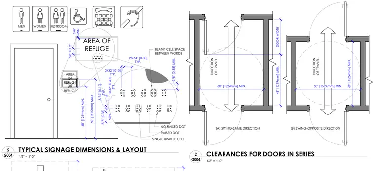
This drawing outlines standard dimensions and layout requirements for accessibility signage and doors in series. It details tactile signage placement heights alongside magnified braille cell dimensions and spacing parameters. Plan diagrams illustrate minimum clearance circles and travel directions for doors swinging in the same or opposite directions.
AREA OF REFUGE AREA OF REFUGE 48" [1219mm] MIN. 60" [1515mm] MAX. MEN WOMEN RESTROOM AREA OF REFUGE MIN. 3/8" 5/8" TO 2" 3/8" [0.38] MIN. BLANK CELL SPACE BETWEEN WORDS NO RAISED DOT TYP. 19/64" [0.30] TYP. 3/32" [010] TYP. 13/32" [0.40] TYP. 3/32" [0.10] MIN. 3/8" [0.38] RAISED DOT SINGLE BRAILLE CELL (A) SWING-SAME DIRECTION (B) SWING-OPPOSITE DIRECTION 60" [1524mm] MIN. 60" [1524mm] MIN. 48" [1219mm] MIN. DOOR WIDTH 60" [1524mm] MIN. DIRECTION OF TRAVEL DIRECTION OF TRAVEL 1/2" = 1'-0" G004 5 TYPICAL SIGNAGE DIMENSIONS & LAYOUT 1/2" = 1'-0" G004 2 CLEARANCES FOR DOORS IN SERIES F h 9 [ ] 1 L / — \ 7 — \ 1 / ) V i o • o • o .. o. / 0(0' oo / O O L • L J □ □□□□ □□□□ □ □□□□ O o o • • o 8 S8B8BB • o OO • o oo • o O 0 oo • o o o oo / V r • o (O O • o V oo oo • • \ oo OO • • \
Members view this detail in full resolution, download the CAD files (SVG, PDF), and can adapt it in the built-in CAD editor — export DXF, DWG, or PDF.
Start membership