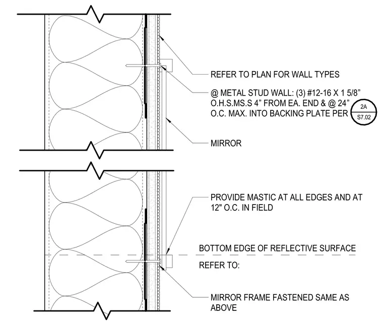
The mirror is mounted to a metal stud wall assembly using three number twelve by one and five-eighths inch fasteners placed four inches from each end and at twenty-four inches on center maximum into the backing plate. Mastic is applied at all edges and at twelve inches on center in the field behind the mirror. The mirror frame is fastened in the same manner as the mirror. Wall types are coordinated per the architectural floor plans, and the bottom edge of the reflective surface aligns with the referenced drawing.
@ METAL STUD WALL: (3) #12-16 X 1 5/8” O.H.S.MS.S 4” FROM EA. END & @ 24” O.C. MAX. INTO BACKING PLATE PER MIRROR PROVIDE MASTIC AT ALL EDGES AND AT 12" O.C. IN FIELD MIRROR FRAME FASTENED SAME AS ABOVE REFER TO PLAN FOR WALL TYPES BOTTOM EDGE OF REFLECTIVE SURFACE REFER TO: 2A S7.02
Members view this detail in full resolution, download the CAD files (SVG, PDF), and can adapt it in the built-in CAD editor — export DXF, DWG, or PDF.
Start membership