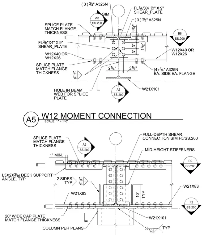
This structural steel detail shows a W12 beam moment connection framing into a W21x101 column with mid-height stiffeners. The top and bottom beam flanges are connected using splice plates matching the flange thickness, secured with three three-quarter-inch A325N bolts on each side of each flange. A full-depth shear connection utilizes three-eighths-inch by four-and-a-half-inch by nine-inch shear plates welded with quarter-inch fillets and bolted with three three-quarter-inch A325N bolts. Deck support angles sized L3x2x3/16 are provided typically at the metal deck level, along with a twenty-inch wide cap plate matching the flange thickness at the column base.
F2 SS.200 A2 SS.200 D2 SS.200 14 / TYP 14 / 14 / 2 SIDES TYP 14 / 14 / B8 SS.200 A6 SS.200 W12 MOMENT CONNECTION SCALE: 1" = 1'-0" A5 A2 SS.200 SIM W21X101 COLUMN PER PLANS FULL-DEPTH SHEAR CONNECTION SIM F5/SS.200 MID-HEIGHT STIFFENERS 20" WIDE CAP PLATE MATCH FLANGE THICKNESS SPLICE PLATE MATCH FLANGE THICKNESS W21X83 W21X83 1" MIN. 10" TYP L3X2X 3 16 / DECK SUPPORT ANGLE, TYP (4) 3 4 / " A325N EA. SIDE EA. FLANGE ( 3 ) 3 4 / " A325N FL 3 8 / "X4" X 9" SHEAR_PLATE FL 3 8 / "X4 1 2 / " X 9" SHEAR_PLATE ( 3 ) 3 4 / " A325N W21X101 W12X40 OR W12X26 W12X40 OR W12X26 SPLICE PLATE MATCH FLANGE THICKNESS SPLICE PLATE MATCH FLANGE THICKNESS HOLE IN BEAM WEB FOR SPLICE PLATE 3" 3" 1 12 / " 1 34 / " 2 1 4 / " 2 1 4 / "
Members view this detail in full resolution, download the CAD files (SVG, PDF), and can adapt it in the built-in CAD editor — export DXF, DWG, or PDF.
Start membership