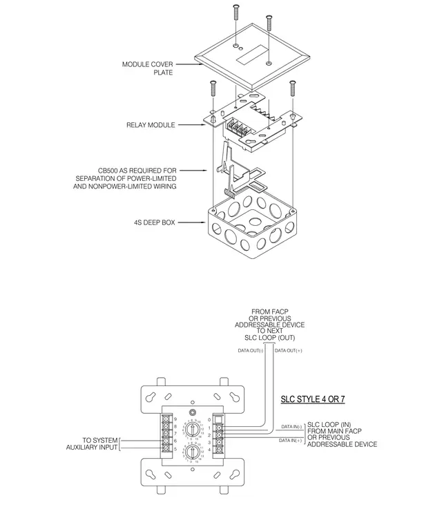
An addressable relay module is mounted inside a 4S deep electrical box using screws and a module cover plate. A CB500 voltage barrier is included as required for separation of power-limited and nonpower-limited wiring. The wiring configuration accommodates SLC style 4 or 7 loops connecting from the main fire alarm control panel, previous addressable devices, and system auxiliary inputs.
MODULE COVER PLATE RELAY MODULE CB500 AS REQUIRED FOR SEPARATION OF POWER-LIMITED AND NONPOWER-LIMITED WIRING 4S DEEP BOX 3 13 2 0 1 14 15 SLC STYLE 4 OR 7 FROM MAIN FACP ADDRESSABLE DEVICE OR PREVIOUS SLC LOOP (IN) TO SYSTEM AUXILIARY INPUT 7 9 7 6 5 8 NC C NC NO 6 8 7 0 1 2 3 4 5 4 6 5 C 8 TO NEXT OR PREVIOUS SLC LOOP (OUT) ADDRESSABLE DEVICE 0 10 3 2 4 11 11 9 15 10 14 13 12 12 1 NO 9 DATA OUT(-) DATA IN(+) DATA IN(-) DATA OUT(+) FROM FACP
Members view this detail in full resolution, download the CAD files (SVG, PDF), and can adapt it in the built-in CAD editor — export DXF, DWG, or PDF.
Start membership